Grayscale PAL signals
I was inspired by Ben Eater’s video on the world’s worst video card to make my own. But in order to prove to myself that I fully understood how it worked, I decided to output composite PAL signals rather than VGA. This post is going to explain how composite signals work rather than how my implementation of the world’s even worsterer graphics card works.
I live in the UK, so here we use PAL signals rather than NTSC. When talking about grayscale, both are very similar, but just different enough to be annoying. I won’t be covering how they differ in this post, because I wouldn’t be able to confirm its accuracy.
How did CRT televisions work?
Although a strange question to ask first, the whole composite signal standard is based around the behaviour of CRT (or cathode ray tube) televisions. Technology connections has a wonderful video explaining the general concepts here, which I will recommend watching for further detail about how the television would produce the signal. I am going to go into much more depth about the actual signal itself, rather than the behaviour of the electron beam as the drawing happens.
Hopefully from this explanation, you should be able to create a terrible graphics card of your own!
Lines
A CRT doesn’t have pixels. Instead, the electron beam gets scanned across in lines. Each line has effectively got an infinite resolution, as you can change the intensity of the electron beam as much as you like (although capacitance will probably stop you from changing it too much).
Potential epilepsy trigger warning in the following video.
With a PAL signal, there are a total of 625 lines per frame, running at 25 frames per second.
However, changing data at 25 frames per second produces noticeable flicker, so rather than update the entire screen 25 times per second, the odd lines get updated first and then the even lines.
This is called interlacing.
So 312.5 lines are updated at 50 frames per second, made up of 313 odd lines, and 312 even lines.
Note that it is no coincidence that the updates happen at exactly the frequency of the AC power.
This provided a very convenient source of a 50Hz timing signal for the TV to use to synchronise with the signal.
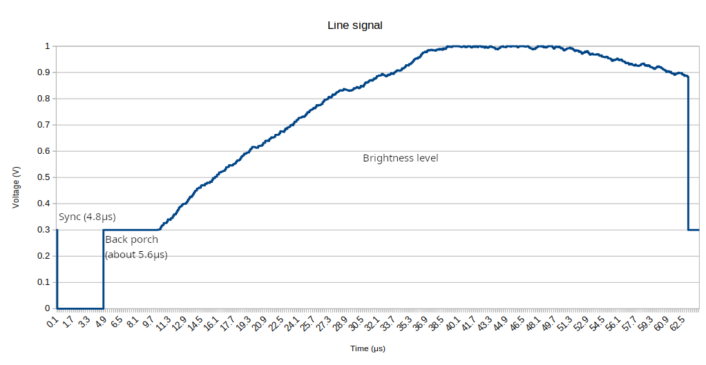
A single line takes 1/625/25 = 64μs to draw.
To control the brightness of a point in a line, set the voltage to a value between 0.3V and 1V. With 0.3V being black, and 1V being pure white.
However, we also need to tell the TV that the line has started, and also give it time to take the beam from the far end of the previous line to the start of the current one.
In order to do that, a line starts with 4.6-4.8μs of 0V.
This tells the TV that the line has started.
There is then something called a back porch.
This is a period of 0.3V which if you try to draw into, will be off the left of the screen.
This time is around 5.6μs before the beam becomes visible on the screen.
After this, voltages between 0.3V and 1V will draw the various brightnesses on the screen.
Eventually, the line disappears off the end of the right hand side of the screen (slightly before the end of the line), at which point the next line starts.
So now we understand how a single line is drawn, and how we tell the TV that we have started drawing a line. Next, we need to cover how to tell the TV that we’re starting to draw a frame.
Synchronisation pulses
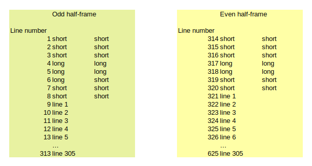
We need to tell the TV that a frame is about to start. However, we don’t just need to tell it that we’re about to start a frame, we also need to tell it that whether it is an odd or ever ‘half frame’. An odd frame will be one which draws all the odd lines, and an even frame one which only sends data for even lines.
It is helpful at this stage to think about ‘half lines’ for reasons that will be clear later. A half line is exactly as the name implies. It takes 32μs to draw a half line.
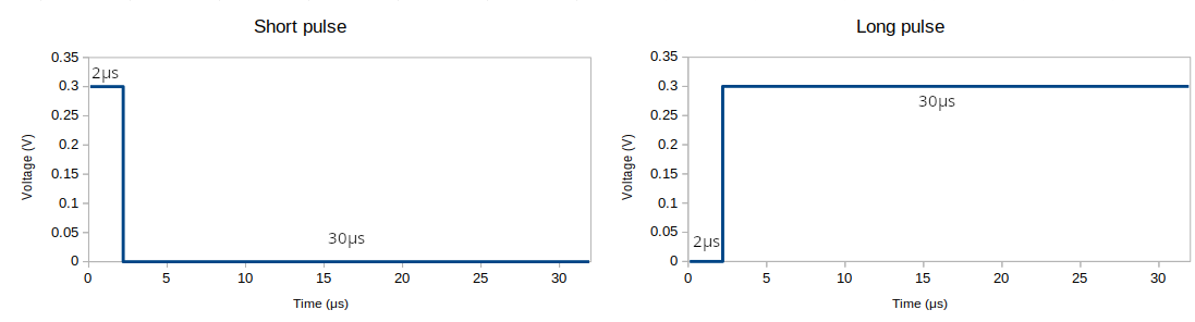
A half line will either be a short sync pulse or a long sync pulse.
A long sync pulse is at 0.3V for 30μs and 0V for 2μs.
A short sync pulse is at 0.3V for 2μs and 0V for 30μs.
To say you’re going to start an odd frame, send 6 short sync pulses, 5 long sync pulses followed by 5 short sync pulses. At that point, send the normal line information for the remaining 305 lines until the end of this half-frame. Then start the even frame with 5 short sync pulses, 5 long pulses and 4 short pulses. And the remaining 305 lines contain the even lines.
Non-interlaced video
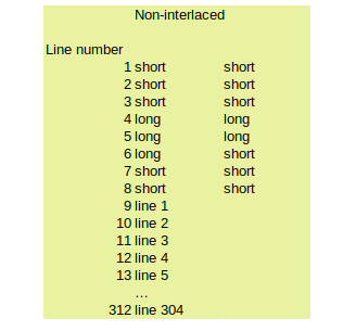
In order to simplify video hardware (and what I ultimately ended up doing for my breadboard video card), you can send the information non-interlaced to the TV. If doing this, effectively send the odd half frame repeatedly rather than switching between odd and even half frames. Note that this means your frame rate will be 1 / (64μs × 313) = 49.92Hz.
However, according to this source, the PS2 on a non-interlaced game will use 304 lines rather than 305. I haven’t personally tried 305 lines to see what happens here, so the way I implemented this was to copy the non-interlaced format and use the odd frame cycle but with 304 lines resulting in a frame rate of 1 / (64μs × 313) = 50.0801Hz. TVs don’t seem to have an issue with this (or at least mine doesn’t).
Implementation notes
You’ll have noticed that I spoke about voltages the entire time here. One thing to note is that the input impedance for a composite cable is 75Ω (you can measure this with a multimeter). In order to actually produce these voltages required, you’ll have to use a suitable resistor to bring your control signal voltage to 0.3V or the analog value for the brightness.
Full demo
Using what Ben Eater teaches in his video about the world’s worst video card, and my research which unearthed the above information, I was able to put together my own video card.
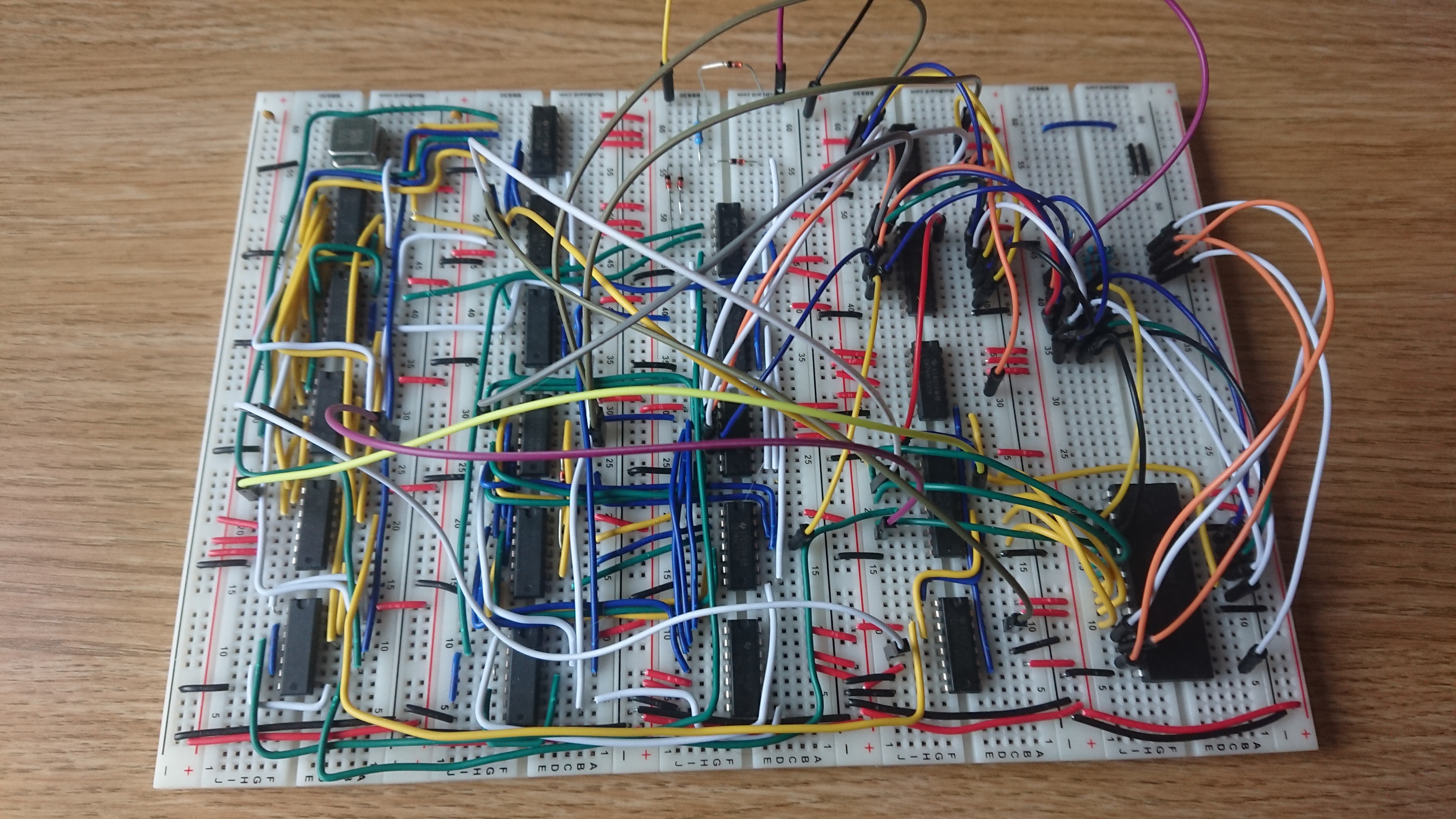
And the result is a 128x128 image on a CRT. Here is a 960FPS video of the output from this circuit.
Another potential epilepsy trigger